Back-to-back transition of the waveguide to microstrip line transition model. In this model, the microstrip line is designed along with a quarter-wave transformer to match the impedance to 50 ohm on a RT/duroid® 6010LM laminate substrate, which is available in the RF Module material library of the COMSOL Multiphysics® software.
3D Wave Propagation in Silicon Waveguide with Rib and Slot Configurations
Application ID: 70551


A 3D silicon waveguide is set up with rib and slot configurations. The meshing includes physics-controlled mesh, with the number of longitudinal mesh elements set to 50 to visualize the wave oscillation.
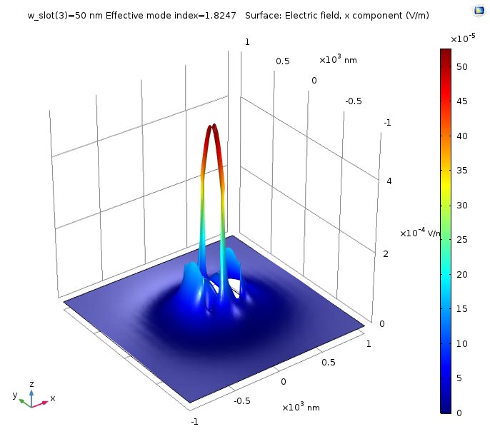
- In a slot waveguide configuration, two high refractive index slabs (3.48) are placed adjacent to the low refractive index slot (1.44). Mode analysis was performed on a 2D cross section of a slot waveguide for an operating wavelength of 1.55 um.
- Modal Characterization of the Plasmonic Slot Waveguide Using COMSOL Multiphysics F. Nocito2, and E. Stoja1 1Department of Information Engineering, Electronics and Telecommunications, Sapienza University of Rome, Rome, Italy.
The detailed discussion of the model setup is discussed in the blog post: 'Silicon Photonics: Designing and Prototyping Silicon Waveguides' in the section 'Designing and Prototyping Silicon Waveguides'.
This model example illustrates applications of this type that would nominally be built using the following products:
however, additional products may be required to completely define and model it. Furthermore, this example may also be defined and modeled using components from the following product combinations:
- COMSOL Multiphysics®and
Slot Waveguide Comsol
The combination of COMSOL® products required to model your application depends on several factors and may include boundary conditions, material properties, physics interfaces, and part libraries. Particular functionality may be common to several products. To determine the right combination of products for your modeling needs, review the Specification Chart and make use of a free evaluation license. The COMSOL Sales and Support teams are available for answering any questions you may have regarding this.
